Helium from Natural Gas

(recommended by William B. Retallick, Consultant)


Over 99% of helium manufactured is as a coproduct of natural gas processing. In addition to recovering helium, nitrogen is removed so that the gas can be sent to market through a pipeline. In these plants, compressors are driven by gas turbines that are fueled with a mixture of methane and nitrogen. This reduces the separation work necessary.


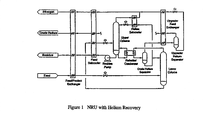
The flow diagram in Figure 1 is from Union Carbide (1) and is called the double-column cycle. In this project, you will find the pressures in the two columns that minimize the power input to the plant. Furthermore, you should consider whether it is more efficient to pass the feed through a turbo-expander rather than a Joule-Thompson valve. The turbine fuel contains at least 45% CH4, with the balance N2, and is delivered to the turbines at 10-15 atm. You should decide which column it comes from.


In a previous design report, Cryogenic Nitrogen Separation (1998), it was shown that a process that removes nitrogen only is uneconomical when the feed cost ($/MMBtu) exceeds about 10% of the value of the sales gas. If the present plant is to be economical, it must result from the sales of the recovered helium ($/MCF).


The design basis is:


      50 Million SCFPD at 800 psig


      Gas Composition (mol%)


Helium

1.0

Nitrogen

15.0

Methane

81.0

Ethane

2.0

Propane

1.0


    1. Pipeline gas is to be delivered at 1,000 psig, containing no more than 2% N2
    2. Crude helium product contains at least 65% He, with the remainder N2 ,,delivered at 1000 psig. Recovery of He is at least 96%
    3. When heat is transferred (irreversibly) between high- and low-temperature reservoirs, the lost work is:  , where T is the temperature of the warm fluid. At cryogenic temperatures, where the temperature levels are lower, the losses are greater. Hence, to avoid increases in the lost work as T decreases, the minimum internal temperature difference (MITD) must be decreased. Use 6 K for your design.
    4. Simplify your calculations with the units K, kg, and atm.
    5. Purchased electricity costs $0.070 per kWh.
    6. The plant will be located in Kansas.
    7. The exchangers are plate exchangers, with literature supplied.
    8. The economics improve rapidly as the percent of He in the feed increases. Within the range of 1% to about 3% He, the plant investment and the power input increase little, if at all. This is because the He is not liquefied anywhere in the cycle. Note that the base case for the design is 1.0% He in the feed. In the economic calculation, you can add an increment of He and subtract an equal increment of N2.
    9. You can display the economics of your process, as was done in 1998, by graphing the investor’s rate of return (IRR) as a function of feed cost per price of sales gas for different percents of He in the feed.
    10.  

      Reference:

      Handley, J. R., and W. C. Miller, "Process Requirements & Enchanced Economics of Helium Recovery from Natural Gas", Society of Petroleum Engineers, Paper 24292, 1992.