Verilog Simulation
Simulating an inverter is very straight forward process. The only
thing we need to do is start Verilog-XL simulator and specify a simulation
file.
Running a Verilog Simulation
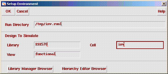
Left click CIW:Tools->Verilog Integration -> Verilog-XL. The Setup Environment
windows
should appear. Fill in the appropriate fields as shown in the figure. It
is recommended that you run your simulation in the local /tmp directory
on the machine. Usually your simulation will run faster.
Left Click OK.
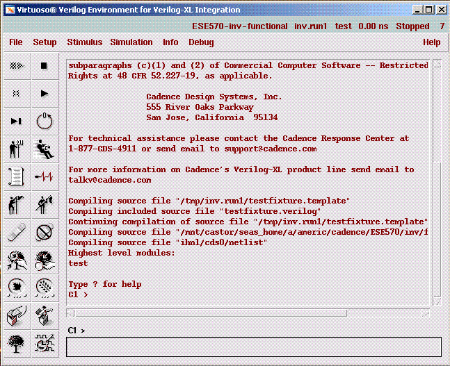
A pop up window will appear. This window is called the Verilog-XL Integration Control window.
Start the simulation process by first clicking on Setup -> Record Signals in the Verilog-XL Integration window.
Make sure to choose All Signals as shown below.

There are (for us) three very important buttons on
the control panel. The two that are currently active (not greyed out) are
Start Interactive in the upper left corner of the panel, and the
View Waveforms button in the lower right corner of the panel. The third
is the Continue button (currently greyed out) - the second button
in the second row of the panel.
Next, click on the top-left button in the list of buttons provided in the Verilog-XL
Integration Control Window or select Simulation -> Start Interactive.
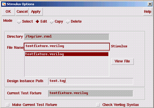
Click on the Stimulus -> Verilog button. You will get the Stimulus Options window as shown below.
Select the "Edit" button and press OK. This will help you create a stimulus
file for the simulation of an inverter.
An Emacs window will appear. Modify the file as shown below
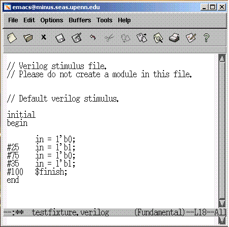
The above stimulus file starts with the input inp = 0 and then changes to 1
at the time instant 25. Then it changes to 0 at 35 time instants later (25+35=60 time instants)
and then to 1 at 75 instants (25+35+75=135 time instants) later. The simulation time is 235 units.
The exact time of simulation is governed by the timescale command in the original functional view file.
Click on the Continue icon (second top icon in the second column) in the Verilog-XL Integration
Control window or select Simulation -> Continue. The Verilog simulation will begin.
Pay attention to the messages that appear in the Verilog-XL Integration Control window to
verify that the simulation is indeed running. You will be notified by those messages in
the window when the simulation has finished.
Next click on the very bottom right icon (View Waveforms icon) or select
Debug -> Utilities -> View Waveform. A pop up window will appear. It is the
window in which you will view your simulation results and is called SimVision.
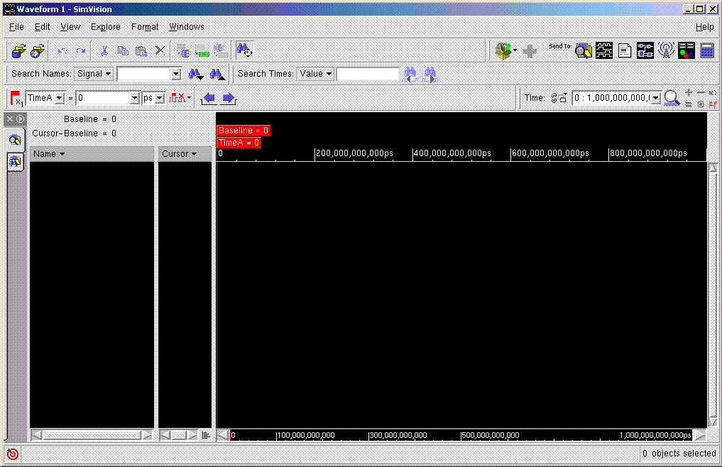
From top right part of the SimVision window, select "Send to Browser"
icon(the icon with a magnifying glass). The following window should open.
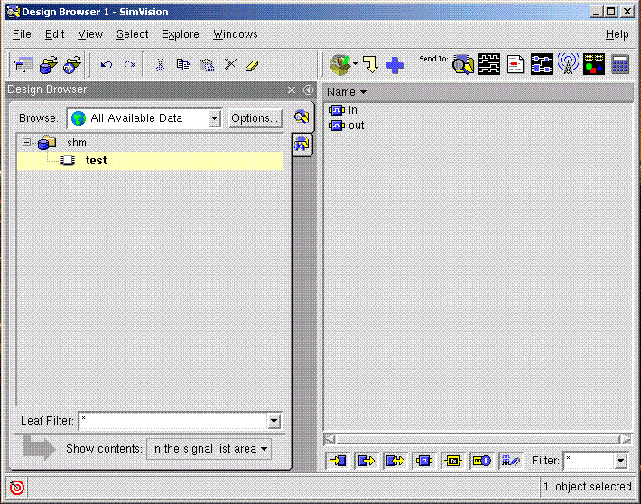
Now select the waveforms that you want to plot. After you selected the waveforms,
press the "Send to Waveform" button(It is located right next to the "Send to Browser" button.
The waveforms should be as follows;
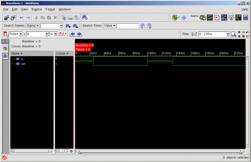
Note: To see the complete waveform, please select View -> Zoom -> Out or the "equality" button
right above the waveform window
